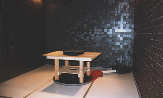
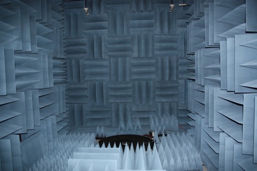
3m pre-scan Immunity/Emissions semi-anechoic chambers are designed to perform ANSI C63.4/CISPR 16-1-4 and IEC 61000-4-3 compliant radiated immunity and emissions measurements. When using this chamber for ANSI C63.4 pre-compliant radiated emissions pre-scan measurements there’s a limited scan height.
C-LCI offers (2) different pre-scan models; our smaller version measures 22’L x 10’W x 10’H and comes only ferrite lined. With ferrite only the chamber can test from 26MHz-1GHz. Our larger model comes with a combination of ferrite tile plus Cuming Microwave’s C-RAM HFP hybrid absorbers; absorbers specifically tuned to receive the hand off and pick up frequencies ≥ ~1GHz.
Frequency ranges for these pre-scan chambers are 26 MHz to 40 GHz (radiated immunity) and 30 MHz to 40 GHz (radiated emission).
[tab:Tech Specifications]
Clear Dimensions* : 12′-0″ (W) x 24′-0″ (L) x 11′-0″ (H)
Operating Frequency Range : 26MHz-18 GHz
Anechoic Absorber Type : Optimized Dielectric-Ferrite/Pyramidal Hybrid
Shielding Effectiveness : 100 dB, Electric, Planewave, Microwave
Radiated Immunity Test Capability : YES
IEC 1000-4-3 Compliance : YES
Uniform Field Area : 1.5m x 1.5m
Field Uniformity Performance : -0 +6dB
Radiated Emissions Test Capability : YES / Prescan w/ limited scan height
ANSI C63.4 Compliance : NO (Pre-Scans for Site Attenuation Correlation)
Site Attenuation Performance : + or – 4dB < 200 MHz, + or – 6 dB 30 MHz – 200 MHz
Test Volume Size : Meter Diameter
Maximum Scan Height : 2 meters
* Inside Clear Dimensions are calculated to the face of the shielded enclosure.
[tab:Installation/Accessories]Prescan Emissions/Immunity Chamber DESIGN:
- Chamber analysis/optimization
- Chamber design & structural engineering
- Hybrid absorber optimization
- Design reviews
- Submittal drawings
- As-built drawings (optional)
SHIELDED ENCLOSURE-
- RF shielded enclosure
- Free standing design – structural support system
- Modular wood-core panel construction
- Waveguide ventilation panels – (2) 12″ x 12″
- Bulkhead connector panels – (1) 12″ x 18″
- RF shielded lighting system –Lighting Options
- RF shielded door – (1) 3′ x 7′ Single leaf access door, low threshold
- Powerline filters – (2) 2×30 amp
- Conduit, one switch, and two receptacles
- Electrical Distribution
- Shielding effectiveness testing per IEEE-299 and MIL-STD 285 at 1 GHz
ANECHOIC ABSORBER – More Info
- Optimized proprietary dielectric-ferrite/pyramidal absorber
- Quality control of absorber manufacture
- Quality control of installation
- Modular ferrite floor absorber
TESTING (Optional)
- Field uniformity testing – IEC 10000-4-3 compliance
- Normalized Site Attenuation testing for prescan emissions – ANSI C63-4 (Limited Height)
- Detailed test plans and reports
EQUIPMENT PACKAGE (Optional)
- 1.2 Meter Diameter Turntable, surface mount, low profile. 800 lb. running load
- Antenna Tower, scans from 1-2 meters, pneumatic polarization standard w/fiber optic interface
- Dual Channel System Controller, Variable speed control, fully IEEE 488.2 compatible, as well as with industry standard automation software.
Warranty –
- 1 year warranty on materials and workmanship
- 3 year warranty on absorber material, under normal conditions
- 5 year warranty on RF shielding effectiveness


