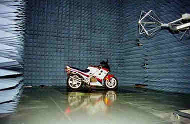
3 Meter Fully Compliant semi-anechoic chambers offer semi-anechoic radiated emissions (RE) and fully anechoic radiated immunity (RI) compliance test capability for most international EMC compliance regulations.
Three meter Fully Compliant Chamber Shielding System:
Our three meter pre-scan Immunity/Emissions enclosure is modular panel construction; the panels are a laminate 26 gauge, electrolytically deposited zinc sheet steel laminated to both surfaces of ¾” thick solid, (structural) core material. These panels have a flame spread of 20 minutes or less as rated by Underwriters Laboratories, Inc. The panels are joined by specifically designed framing members that clamp the edges of the panels and provide constant, low impedance joints with the shielding elements of the chamber. Weld nuts are on 3” centers and our corners are welded; no screws are used and nothing penetrates our chamber’s shielding.
Three meter Fully Compliant Chamber Shielding Effectiveness:
|
Magnetic Fields |
Electric Field |
Plane Wave |
Microwave |
|
1KHz – 28dB |
1KHz – 120dB |
100MHz – 110 + dB |
1GHz – 110 + dB |
|
10KHz – 58dB |
10KHz – 120dB |
400MHz – 110 + dB |
10GHz – 110 + dB |
|
200KHz – 100dB |
100KHz – 120dB |
1GHz – 110 + dB |
18GHz – 110 + dB |
|
1MHz – 110dB |
10MHz – 120dB |
|
|
|
|
100MHz – 120dB |
|
|
Three Meter Fully Compliant Chamber Design:
A 3 meter fully compliant chamber’s length and width depend upon the size of the DUT; our most popular model comes with a 2 meter turntable. The specification mandates the source antenna scan up to 4 meters above the ground plane so the height is set at ~20’.
Cuming Microwave’s C-RAM HFP hybrid absorbers are specially designed to match the impedance of the ferrite tiles and can safely withstand continuous field intensity of up to 400 V/m and intermittent field intensity of up to 750 V/m. This safely exceeds the field intensity requirements of most commercial RI tests.
Radiated Emissions Testing:
Our three meter fully compliant chamber can be used to perform full compliance testing for ANSI C63.4, FCC parts 15 & 18, EN 50147-2, CISPR 11/EN55011, CISPR 16/EN55016, CISPR 22/EN55022, VCCI V-3/2003.04, SAE J551 and SAE J1113.
Radiated Immunity Testing:
C-LCI’s three meter fully compliant chamber can also be used to perform full compliance testing for IEC 61000-4-3/EN61000-4-3 and SAE J-1113 requirements.
Our 3m fully compliant chamber range lengths field uniformity of 0 – 6 dB is achieved in the test aperture over the frequency range of 26 MHz to 18 GHz. The test aperture is a vertical plane 1.5 meter x 1.5 meter at an elevation of 0.8m to 2.3m above the ground plane, following the field uniformity test procedure of IEC 61000-4-3.
Turnkey Systems
Cuming-Lehman Chambers, with the collective experience of our teaming partners feel confident that we provide an overall fully compliant technical package that offers you a lowest risk, budget friendly solution while meeting all your testing requirements. All of our products are designed to work together for maximum efficiency and performance.
For additional information or a quote contact us today.
[tab:Tech Specifications]
Inside Clear Dimensions : 20′-0″ (W) x 30′-0″ (L) x 19′-0″ (H)
Operating Frequency Range : 26MHz-18GHz
Anechoic Absorber Type : Optimized Ferrite/Urethane Foam Hybrid
Shielding Effectiveness : 100 dB, Electric, Planewave (IAW Mil-Std 285)
Radiated Immunity Test Capability : YES
IEC 1000-4-3 Compliance : YES
Uniform Field Area : 1.5m x 1.5m
Field Uniformity Performance : -0 +6dB (IAW IEC 10000-4-3)
Radiated Emissions Test Capability : YES
ANSI C63.4 Compliance : YES
Site Attenuation Performance : + or – 4 dB (IAW ANSI C63.4-1992)
Antenna Calibrations : Free Space Antenna Factors (IAW ANSI C63.5-1998)
Test Volume Size : 2.0 meters (dia.) x 2.0 meters (high)
Maximum Scan Height : 4 meters
* Inside Clear Dimensions are calculated to the inside of the shielded enclosure.]
[tab:Installation/Accessories]THREE METER CERTIFIED EMISSIONS CHAMBER
(Baseline Chamber Design/Components)
DESIGN
- Chamber analysis/optimization
- Chamber design & structural engineering
- Hybrid absorber optimization
- Design reviews
- Submittal drawings
- As-built drawings (optional)
SHIELDED ENCLOSURE
- RF shielded enclosure
- Free standing design – structural support system
- Modular wood-core panel construction
- Raised access floor (12″ deep w/ removable panels)
- Waveguide ventilation panels – (4) 12″ x 24″
- Bulkhead connector panels – (2) 12″ x 24″
- RF shielded lighting system – (4) Corner Spotlight fixtures, (4) 250 watt Metal Halide Highhat Light Fixtures
- RF shielded door – (1) 4′ x 7′ Double leaf access door, low threshold
- Powerline filters – (1) 2×30 amp, (1) 2×100 amp
- Brass Ground Stud
- Conduit, switch, and two receptacles
ANECHOIC ABSORBER – Ferrite Tile
- Optimized proprietary dielectric/ferrite absorber
- Quality control of absorber manufacture
- Quality control of installation
- Modular ferrite floor absorber
ANECHOIC ABSORBER – Urethane Foam
- Optimized proprietary urethane foam absorber
- Quality control of absorber manufacture
- Quality control of installation
TESTING
- Shielding effectiveness testing – MIL-STD 285 compliance test
- Field uniformity testing – IEC 10000-4-3 compliance
- Normalized Site Attenuation testing – ANSI C63.4 compliance
- Detailed test plans and reports
EQUIPMENT PACKAGE (Optional)
- 2.0 meter diameter turntable, supports a 4,400 lb. distributed load, minimum pit depth of 12″ required
- Antenna Tower, scans from 1-4 meters, pneumatic polarization standard w/fiber optic interface.
- Dual Channel Controller-variable speed control through front panel or GPIB interface. Fully IEEE 488.2 compatible, as well as with industry standard automation software


